


In the FAQ section we have documented and answered the most common support inquiries for you. This area is still under development and will be continuously expanded with further topics. We are starting with the ELS NFC category.
To ensure fast and effective support, please have the following information ready before contacting our technical support:
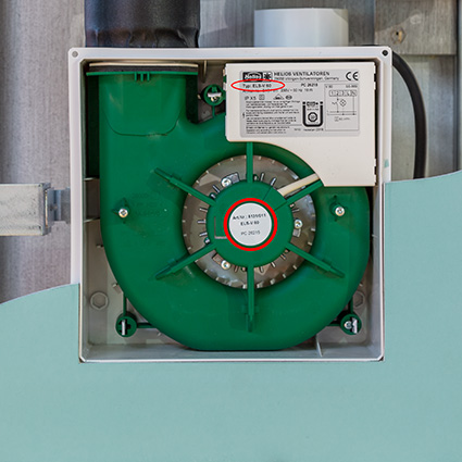
- The data from the type plate of the product in question. Catalog details are not sufficient for clear identification and diagnosis.
Recommendation: Keep a photo of the type plate ready when contacting our support. - If other components are connected to the product, please also have the type plate data for these components available.
Visit HeliosSelect to access detailed information and documents for all products in the Helios series program.
- Product information
- Technical data
- Dimensional drawings
- Wiring diagrams
- Data sheets
For a complaint or replacement part order, the data from the type plate is required.
Since there may be small technical differences within a product series due to changes, catalog data alone is not sufficient.
In principle, we try to maintain the dimensions of the fans during development and updates.
However, due to ERP guidelines, this is not always possible. The current dimensions of our fans can be found on HeliosSelect.
Please keep in mind that a fan should not be determined by its dimensions, but by its operating point and application conditions.
Components for the ELS mono tube ventilation system generation (ELS-VE, up to 2007) are still being manufactured and are officially distributed through wholesale channels.
Please contact your wholesaler and provide the known article number of the respective fan unit.
The ELS mono tube ventilation system operates with a constant volume flow. The higher the system pressure, the higher the fan speed — and therefore the noise level.
First, check the air filter. If it’s clean, please contact your installer to investigate the problem further.
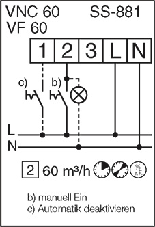
The correct wiring diagram is printed directly on the respective fan unit.
A full overview of wiring diagrams can be found on the last page of the corresponding installation and operating manual.
Please make sure to match the wiring diagram with the exact model designation.
Example: Wiring diagram for ELS VNC 60
A dirty filter can cause reduced performance and increased noise levels. If the filter is clogged, the motor winding may not be adequately cooled, leading to faster wear of the ball bearings. In extreme cases, a completely blocked filter can cause the unit to overheat and result in motor failure.
For this reason, the filter should be checked regularly for dirt and cleaned if necessary. No special expertise or tools are required for cleaning.
For more information, please refer to the installation and operating manual.
Activities other than showering can also raise the relative humidity. For example, a damp towel releases moisture into the room air.
In addition, a drop in room temperature automatically increases the relative humidity. This means the fan may temporarily switch on in the evening after the heating is turned off.
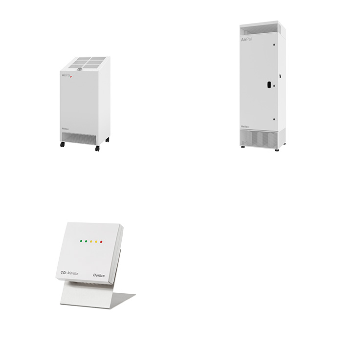
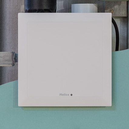
No, the surface-mounted housing is available in white as standard.
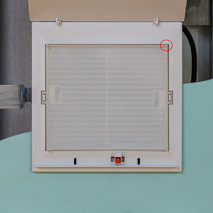
The filter is equipped with a cleaning indicator that is integrated into the façade and visually alerts the user to the need for cleaning. The filter should be cleaned at regular intervals, e.g. every six months, depending on the degree of soiling, so that the ventilation function is guaranteed in the long term. All ELS types are equipped with a permanent filter for this purpose, which can be cleaned simply and easily in the dishwasher - this saves you having to buy expensive disposable filters.
The devices are protected against water jets (IPX5) and comply with protection class II. They can therefore be safely installed in area 1 of wet rooms – for example, directly in the shower or above the bath.
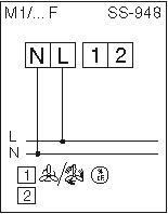
The ELS is designed in protection class II, so the protective conductor cannot be connected. It ends on a terminal provided by the customer.
All ELS NFC and ELS EC types require a permanent power supply at terminals L and N. This is indicated by a solid line in the circuit diagram.
The ELS-V series can be operated without a permanent phase. The ELS-VF/VP/VN/VNC types also require a permanent power supply.
You can easily view all technical properties and values at HeliosSelect.de.
Please note the possible causes and the corresponding recommendations for action:
Filter dirty or clogged: Check, clean or replace filter.
Insufficient air flow: Check the supply and exhaust air ducts and keep them clear.
Incorrect voltage: Check connections and adjust if necessary.
Damaged bearings: Replace fan insert.
Contamination: Clean the appliance thoroughly.
Insufficient air flow: Expand air flow openings.
Check that the non-return flap is correctly installed and can move freely. Rattling is often caused by atmospheric influences, for example when gusty wind loads hit the roof bonnet and create a negative pressure (suction effect) in the ventilation system. A sudden equalisation of pressure, which can occur when the door is opened quickly without air flow (e.g. door grille), triggers the non-return flap. To reduce these effects, you can install a flow resistance in the pressure-side pipework.
Check the settings and check whether there may be different pipework, different levels of filter contamination or an insufficient downstream opening.
Interval runtime: Period of time during which the fan runs in this function.
Interval pause time: The period of time between running times during which the fan is switched off.
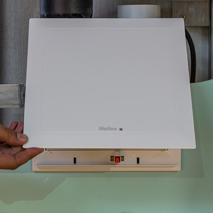
1. Open the fassade (maximum opening angle: 120°)
2. Remove the filter
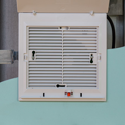
3. Read the model designation through the blades, or remove the fassade unit by loosening the two screws
Yes, ELS NFC can also be used without an NFC-capable smartphone. In this case, the device works with the preset factory settings. Subsequent adjustments are possible at any time. In principle, almost every modern smartphone has an NFC interface.
For Android devices: Open the “Settings” and enter “NFC” in the search bar. If no results are displayed, your smartphone probably does not have NFC.
For iPhones: All iPhone models from the iPhone 7 onwards support NFC.
Note on app compatibility: With the next update, the app will automatically check whether the device used supports NFC. If this is not the case, a corresponding warning will be issued (for example, when used on an iPad).
The position of the NFC antenna can vary depending on the manufacturer and model of the smartphone. On iPhones, it is usually at the top, while on Android devices it is usually on the back of the device.
Open the app and start the connection. Hold your smartphone to the NFC points of the ELS. The configuration data is now loaded. Then remove the smartphone, make the desired changes and hold the smartphone to the NFC point again to start the transfer.
To establish an NFC connection, the smartphone should be held as close as possible and parallel to the control unit. This ensures optimum energy transmission between the smartphone antenna and the antenna of the ELS control unit. The distance required is comparable to that for contactless payment with a debit card: the device must be placed directly on or positioned at a very short distance from the reader.
The ELS app is used exclusively for parameterising and adjusting the device settings.
Important: The airflow rates must be set by a specialist installer, as compliance with the DIN specifications is essential. The ELS app is therefore expressly not intended for end users.
Thanks to the NFC function, you can conveniently set the desired parameters using the Helios ELS app. A particular advantage is that this is possible while the device is still packaged - without any power supply or internet connection. It is no longer necessary to open the device, for example to make DIP switch settings.
| Airflow | Startup delay | Overrun time | Interval time | |||||||
| level 1 | 35 m³/h | level 1 | 45 sec. | level 1 | 15 min | Intervall runtime | 0 min | |||
| level 2 | 60 m³/h | level 2 | 45 sec. | level 2 | 15 min | Intervall pause time | 0 hrs | |||
| level 3 | 100 m³/h | level 3 | 45 sec. | level 3 | 15 min | |||||
| Basic ventilation | 0 m³/h | |||||||||
| Interval ventilation | 0 m³/h | |||||||||
ELS NFC F has the same factory settings as the model ELS NFC (see question B-01), but with the following, additional humidity settings:
| Humidity settings: | |
| Dehumidification mode | comfort |
| Maximum value relative humidity | 90 % |
| Threshold relative humidity | 60 % |
| Max. airflow humidity control | 60 m³/h |
ELS NFC P has the same factory settings as the model ELS NFC (see question B-01), but with the following additional presence settings.
| Presence settings: | |
| Overrun P-sensor | 15 min |
| Maximum airflow P-sensor | 60 m³/h |
ELS NFC CO2 has the same factory settings as the model ELS NFC (see question B-01), but with the following, additional CO2 settings:
| CO2 settings: | |
| Maximum value CO2 | 1400 ppm |
| ThresholdCO2 | 800 ppm |
| Maximum airflow CO2 | 60 m³/h |
ELS NFC VOC has the same factory settings as the model ELS NFC (see question B-01), but with the following, additional VOC settings:
| VOC settings: | |
| VOC mode | comfort |
| Maximum value VOC | 250 VOC |
| ThresholdVOC | 100 VOC |
| Maximum airflow VOC | 60 m³/h |
Programming is carried out by the customer via the ELS app and cannot be ordered in advance.
Yes, you can find out more in the installation and operating instructions.
Yes, the ELS NFC series is compatible with all housings built from 2008 onwards.
No, as contacting with the control board can only be carried out at the Helios factory.
No, but the ELS-NFC devices offer a larger selection of airflows compared to the previous ELS-EC devices. The airflow can be individually adjusted for each stage, with options of 100, 90, 80, 70, 60, 50, 45, 40, 35, 30, 25, 20 and 15 m³/h. In addition, the airflows can be set separately for basic ventilation, intermittent operation and sensor operation.
The parameters can be transferred to the ELS NFC both without mains voltage and during operation.
Both the flush-mounted and surface-mounted housings have a pre-punched opening intended for the mains cable. In addition, there are further break-out openings located on the side or on the rear, which are intended for the control cable of the ELS-0-10-V variant. Further information on this can be found in the Installation and operating instructions ELS-GU or ELS-GAP.
If 7.5 m³/h is selected, ELS operates in intermittent mode, with the fan running alternately at 15 and 0 m³/h.
There may be several reasons for this: The fan is operating in intermittent mode or the presence detector is reacting to a heat source.
Position the smartphone correctly: Hold the smartphone directly against the contact point. This is located in one of the four corners of the ELS and varies depending on the installation situation.
Check the minimum requirements: Ensure that your smartphone fulfils the minimum requirements (at least Android ... or iOS ...) and has an NFC function.
Check the fan insert: Check whether your fan is NFC-capable. Open the façade, remove the filter in accordance with the installation and operating instructions and check the rating plate to see whether ‘ELS NFC...’ is noted on it. If ‘NFC’ is not in the type designation, the fan cannot be programmed with the app.
Further steps: If no connection is established, follow the instructions under "How close do I have to hold my smartphone to the ELS to establish an NFC connection?" and the information on the installation situation in the installation and operating instructions.
Read out operating status: Use the app to read out the current device status and information of the fan.
Check terminals: Check whether the fan is being controlled via terminals 1, 2 or 3.
Function of the terminals: Check the setting parameters for the respective terminal via the app to ensure that all settings are configured correctly.
Check operating mode: Check whether a basic ventilation level is set or whether the fan is sensor-controlled according to humidity, CO₂ or VOC.
As the NFC connection is not a permanent connection, the data read out only shows the status at the time of connection. Changes to the system require the NFC connection to be re-established in order to display updated data.
Wait until the app has fully loaded the data before removing the smartphone. Do not remove the smartphone as soon as the connection is established, otherwise the charging process will be interrupted.
To establish an NFC connection, the smartphone should be held as close as possible and parallel to the control unit. This ensures optimum energy transmission between the smartphone antenna and the antenna of the ELS control unit. The distance required is comparable to that for contactless payment with a debit card: the device must be placed directly on or positioned at a very short distance from the reader.
Terminal L has no voltage and the device is in offline mode.
The airflow rate setting of 7.5 m³/h can only be achieved by operating the fan intermittently. In this mode, the fan alternates between active and pause time. Basic ventilation operation always starts with the pause time. During the active time, the fan runs at 15 m³/h, while it is switched off during the pause time. In this case, the airflow rate display shows either ‘15’ or ‘0’ m³/h. In addition, the airflow requirement is displayed to indicate the operation of the basic ventilation.
Yes, please refer to the ELS NFC installation and operating instructions, chapter ‘Status LED’. The device status can also be read out via the Helios ELS app.
The saved projects can be saved in the app library and shared with other people by email, for example. The ELS app must be installed in order to read the saved data.
In the app library under ‘Templates Helios’ you will find the factory settings for each ELS NFC device type. These settings can be transferred to a device of the same type at any time via the app.
The current values are displayed for each new contact and can then be adjusted. However, the settings may only be changed by an authorised technician.
The overrun comes into effect when the level is switched. Special case: A time that is already running is not extended.
The switch-on delay (EVZ) also counts as a switchover delay. Special case: A time that is already running is not extended.
Example of special case:
ELS is off > level 1 is switched on > EVZ of level 1 starts > level 2 is switched on in the meantime: In this case, the ECC of stage 1 runs down completely and ELS then switches directly to stage 2. (The overrun logic works accordingly).
In general, the last terminal addressed is given priority. However, if several terminals are addressed at exactly the same time, the terminal with the higher level is decisive.
Note: Depending on the airflow rate setting, the airflow rate in the higher level may be lower than in the smaller level.
Yes, this is possible by setting the following parameters: The humidity sensor controls the airflow continuously depending on the measured humidity value. The humidity control can be further specified by setting a threshold value, such as the relative humidity. Please refer to the installation and operating instructions.
Connect the L and N terminals and then select the desired airflow for the basic ventilation in the app.
Select the value ‘0 m³/h’ for basic ventilation in the app.
No, the airflow can be selected individually for each stage.
Yes, the assignment of the levels is freely selectable.
Yes – the airflow rate can be individually adjusted for each stage, with options of 100, 90, 80, 70, 60, 50, 45, 40, 35, 30, 25, 20 and 15 m³/h. In addition, the airflow rates can be set separately for basic ventilation, intermittent operation and sensor operation.
No, a plausibility check is carried out when configuring and transferring data to ELS NFC. This check ensures that the transferred parameter set is compatible and valid with the connected fan type. Only one transfer can be made to the same type, for example from ELS NFC F to ELS NFC F.
Two modes are available: Comfort and Intensive.
Comfort mode: If the threshold value is exceeded, the airflow is adjusted proportionally to the measured value. This enables energy-efficient and quiet reduction of the indoor humidity.
Intensive mode: As soon as the threshold value is exceeded, the fan switches directly to the maximum airflow in order to reduce the indoor humidity quickly.
In the device status, tap on ‘Airflow adjustment’ and select the desired value.
Info display on mobile phone: Connection successfully established. Configuration successfully accepted.
This can be realised externally via a weekly timer that controls stages 1/2/3. The fan can also be operated depending on the sensor. Basic ventilation and interval ventilation can also be set.
The current configuration of the fan can be read out via the app. The parameters can be compared with the factory settings, which can be displayed in the app library.
The airflow rate setting of 7.5 m³/h is only possible by operating the fan intermittently. The fan alternates between active time and pause time. Basic ventilation operation always starts with the pause time. During the active time, the fan runs at 15 m³/h, while it is switched off during the pause time.
For all ELS NFC with sensor (ELS NFC P, ELS NFC F, ELS NFC CO2, ELS NFC VOC), interval operation can also be set in addition to sensor operation.
Yes, the sensor can be deactivated for a maximum of one hour. If the sensor control is to be deactivated beyond this time, the deactivation contact must be operated again for the following hour.
The last manual request has the highest priority and overrides all other operating modes. This is followed by the sensor request, which overrides intermittent operation and basic ventilation. Intermittent operation again has priority over basic ventilation.
When starting the app, a warning appears that settings may only be made by specialised personnel. It is also not obvious to tenants that this is an NFC-enabled device, as there is no labelling on the inner panel. The device looks as usual.
There is a preconfigured factory setting for each device type, which can be called up at any time via the app and transferred to ELS NFC. Additional configurations can be created and saved by the app user.
Yes, the sensor readings are saved. Depending on the variant, the relative humidity and temperature, the VOC index value or the CO2 measured value are recorded. The data is saved cyclically and can be sent to Helios customer service as an ‘error report’ via the app. Helios customer service via the app.
All ELS types (ELS NFC and all ELS NFC with sensor) store the data records on the NFC chip. The storage time is approximately 24 hours.
Support will check and analyse your error description and the transmitted data. Please make sure that you provide as detailed error description, as this is essential for processing.
Yes, please send the fault description including a precise description of the problem (what is the fault). This facilitates processing and ensures a faster solution.
After submitting the data, our support department has access to the error report and can use it for analysing and processing.
All ELS types (ELS NFC and all ELS NFC with sensor) can store a total of 142 data records on the NFC chip, which corresponds to a storage time of around 24 hours. A data record contains the following information:
Running time: The device measures the relative time, without date or time. The runtime corresponds to the time during which the device's power supply is switched on.
NFC with sensor ONLY: Sensor measured values, depending on the variant: relative humidity and temperature, VOC index value or CO2 measured value.
Motor status: Whether the motor is switched on or off.
Airflow request: The requested airflow rate.
Cause of the airflow request: For example, manual request, sensor request, basic ventilation or interval operation.
Status of the manual terminals: Status of terminals 1-3, e.g. actuated by light switch.
LED code: Contains error statuses, stop times in sensor operation and other relevant information.
The data is saved cyclically every 10 minutes and can be sent to Helios customer service as an ‘error report’ via the app.
In addition, 8192 data records can be stored in the internal EEPROM memory for the sensor types. This corresponds to a data volume of around one week. Data is saved cyclically every 10 minutes as well as irregularly in response to events, e.g. manual requests or changes to the sensor values.
The data can only be read out at Helios via the GUI.
No, depending on the type, the run-on time and the switch-on delay can also be set on the lower levels.
For the ELS-VNC and ELS-VF models, the switch-on delay can be deactivated at the highest levels.
In the case of the ELS-VF model, this is also possible at lower levels (if available).
To do this, set DIP switch 6 to ON and briefly apply a switch-on pulse to the corresponding input terminal. The fan will then operate during the set overrun time.
The automatic mode (e.g., humidity control) will, of course, remain active.
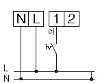
The connection must be made according to the desired operating mode:
1. The fan should only switch on based on humidity:
2. The fan with humidity control, in addition, should switch on when the light switch is activated:
All models of the MiniVent M1 series with deactivatable switch-on delay (except for the standard models of M1/100 and M1/120) can be switched on via a switch-on pulse to terminal 1 using a push button.
The fan will then run for the duration of the preset overrun time after each button press.
Any set automatic programs will remain unaffected.
We recommend using the 2-stage switch MVB only for the standard models M1/100, M1/120, and M1/150.
For all other models with additional functions, MVB is not suitable.
For the MiniVent M1/..F models, the fan is activated based on humidity control.
Factory setting 70/60: The fan starts at 70% relative humidity and runs until the humidity drops to 60% RH. The fan will shut off after a maximum of 2 hours.
The humidity threshold can be adjusted using DIP switches 4+5.
Caution: The mold threshold is reached at around 65% RH. Settings above the factory default may lead to mold growth. Settings below the factory default are rarely reached in practice.
Other factors besides showering can also increase the relative humidity. For example, a damp towel releases moisture into the room air.
Additionally, a drop in temperature automatically increases the humidity. Therefore, the fan often runs temporarily in the evening after the heating is turned off.
The backdraught shutter reacts to sudden pressure equalization, such as when a door is opened quickly without proper air intake.
The room to be ventilated does not have the required unobstructed air intake. The air intake opening (e.g., door grille) should have a minimum area of 150 cm².
Yes, system adjustment is the installer’s proof that the unit is operating within its permitted performance range.
It is also the only way to ensure that the calculated air volume for each room is actually achieved.
To maintain a continuous and controlled air exchange, the KWL ventilation unit with heat recovery should not be switched off.
In exceptional cases (e.g. strong odors from outside), switching it off is of course possible.
Switching off the ventilation unit may lead to condensation and, over a longer period of time, to moisture damage to the ventilation device.
The filters in the KWL unit must be checked and replaced at regular intervals.
Detailed information can be found in the relevant installation and operating manual.
The KWL EM 45 is connected to terminals 1 and 2 on the control unit using two wires.
The external contact must be programmed to "supply air mode" in the control unit.
The fan to be monitored is connected to terminals N" and L". Mains voltage must be applied to N' and L'.
In some cases, it may be necessary to adjust the switching threshold using the potentiometer.
During summer nights, the bypass directs cool, filtered outside air past the cross-flow heat exchanger and directly into your rooms. This increases living comfort by enabling natural cooling of the rooms overnight.
The bypass shutter opens when the following criteria are met:
- The user-defined time period is active
- The outdoor air limit has been exceeded
- The set room temperature has been exceeded
- The incoming outdoor air is cooler than the room temperature
The bypass shutter closes when either the outdoor air limit or the target room temperature is no longer exceeded.
If the air inside the building is colder than the incoming outside air, increased condensation can occur in the supply air section.
Since the supply air section typically does not have a condensate drain, it may lead to water leakage from the unit, as well as damage and mold growth.
Only units equipped with a condensate drain on the supply air side can safely close the bypass under these conditions.
In bypass operation, heat recovery is bypassed, and the (filtered) outside air is directly supplied into the building.
For excessively warm outdoor temperatures, we recommend setting the KWL unit to reduced ventilation (level 1). This ensures that controlled air exchange can still be maintained.
Some of our KWL units (KWL 170 W, KWL 200 W, KWL 250 W, KWL 300 W, KWL 360 W, KWL 470 W, KWL 500 W) feature this additional function.
Even if the room temperature is cooler than the outside temperature, the bypass shutter will close. However, a plug must be removed in the KWL unit to allow condensate drainage.
This function is essential when using an air conditioning system in addition to the ventilation unit!
Due to the different building materials in the rooms, the moisture introduced is absorbed to different degrees. Constantly opening windows and doors contributes to a strong mixing of the room air (especially in the transition months).
With the use of the HygroBox, a cleaning process takes place 1-4 times a day. The drier the incoming air, the more water is required to reach the desired target humidity.
The higher the chosen supply air temperature, the more water is needed to achieve the desired target humidity. (HX diagram)
First of all, it has to be ensured that there is enough water in the internal tray. In addition, the permitted total volume flow must not be exceeded. It is important to ensure that the actual temperature matches the target temperature.
You need admin rights to make this setting. Go to Configuration and select Fire protection. Then press the “down” button three times and change the “Fire alarm input” setting from “Normally open” to “Normally closed”.
No, installing our factory-supplied condensate pumps keeps the pipe route very short. This ensures that the condensation water drains into the siphon pump.
No, this should not be done due to the differing pressure conditions. It may result in unwanted noise or cause the condensate water to not drain properly (due to negative pressure).
In the Helios AIR1 unit, condensate occurs on different sides of the heat exchanger (summer or winter) depending on the temperature difference. If both connections are used, two siphons or condensate pumps must be installed.
This error is displayed when there is no main power connection or when the connection is incorrect. Further steps: check the voltage and verify the internal wiring.
The following points should be checked:
- Check the operating mode
- Set the timer
- Check the error indicator
- Is the external control active?
- Is the main switch turned on?
- Is there voltage present?
- Is the control panel display working? da?
If problems persist, please feel free to contact us.
It must be ensured that the outdoor and indoor temperature limits have been reached, the time frame is correct, and the "Minimal" setting has been activated.
EC fans are generally powered via a 230 V connection and controlled using a 0–10 V signal. A 10 V control voltage output is available directly on the fan. Frequent switching on and off of EC fans can be performed via the 0–10 V control input or, depending on the model, via the release input (by connecting the control voltage output directly to the control input). This method is gentle on the electronics and ensures a long service life. Controlling via the mains supply (on/off) is not recommended. In general, a time interval of at least 120 seconds must be observed when switching the mains power off and on. Manual control, e.g. using PU or PA controllers, is possible.
Yes, according to our specifications. Without motor protection, a AC-motor would be destroyed in case of a fault. The motor protection ensures that the power supply is switched off if a fault occurs. Without motor protection, the warranty may be voided.
For EC motors, motor protection is already integrated in the electronics.
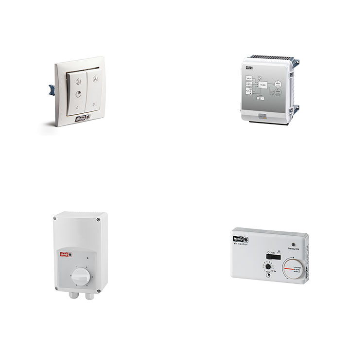
With the electronic speed controllers, the motor can be switched on and off by pressing the switch. The speed can be adjusted by turning the switch.
Under the cover, there is a potentiometer to adjust the minimum speed.
The speed controller can be integrated into many common light switch programs. Only the controller insert is required from the delivery scope. Frame, central insert, and rotary knob must be added from the respective manufacturer’s light switch system (rotary dimmer program). In some cases, the illuminated function may need to be omitted.
The round shaft of the speed controller has a diameter of 4 mm and can be extended to 6 mm using an adapter piece (included in the delivery).
The control potentiometers P differ in the second letter between a flush-mounted and surface-mounted version. The distinction between 24 and 10 refers to the supply voltage of the integrated LED, which depends on the supply voltage of the fan. All types control the fan with 0-10 V.
Depending on the power supply of the motor control, a different number of EC fans (with or without LED) can be controlled. Details can be found in the installation and operating instructions of the respective EC series.
Depending on the power supply of the motor control, PA/PU units with or without LED can be connected. Details can be found in the installation and operating instructions of the respective EC series.
The function of the LED depends on the fan type. For some smaller models, the LED has no function. By default, the LED indicates any malfunctions:
LED green = no malfunction, LED red = malfunction.
For small AC fans, a thermal contact is connected in series with the winding. If the motor overheats, it reliably switches off.
For large, non-voltage-controllable three-phase motors, temperature monitoring is not always integrated. Motor protection is then provided via a classic motor protection switch, which must be set to the rated current and installed on site.
EC motors have internal motor protection. The electronics reliably shut down the motor in the event of a fault.
No, reverse operation is not possible.
No, integration into the building's existing control system must be carried out by a qualified electrician.
The flow monitor or airflow sensor is installed in the duct section between the supply air fan and the electric heating element. A minimum distance of 0.5–1.0 m from non-combustible parts must be maintained. Installation after the heating element is not recommended. Ensure there is a sufficient calming section before and after the sensor.
The duct sensor TFK is installed on the outlet side behind the electric heating element. The greater the distance between the heating element and the duct sensor (minimum 3 m), the better the control behavior.
The required temperature safety components – safety temperature limiter (STB) and safety temperature monitor (STW) – are already integrated in the EHR electric heating element and must be wired on site.
An on-site safety circuit including the STW, STB, and airflow monitor must be implemented.
Due to the design characteristics of the heating element, a overrun time is not required.
The unit can be installed in either a vertical or horizontal position. Ensure that the connection housing is not located at the bottom.
No. The temperature control components are designed for a control range of up to 30 °C.
As the manufacturer, we do not take responsibility for the on-site installation of the appliances. The contracted electrician is responsible for the electrical connection and planning. Relevant regulations and guidelines must be observed.
For our 3-phase electric heating registers, we offer the EHSD 16 and 30 temperature controllers. These can be controlled via a 0–10 V signal. Helios does not offer 0–10 V control options for 1- and 2-phase electric heating registers.
It is not possible to connect SWE directly to an EHR-Rxx TR electric heating element. The release takes place with protection provided by the customer.
The minimum flow velocity is set to 2 m/s on the front panel of the control unit.
The air flow sensor is installed on the inlet side in front of the electric heater or - if not possible - on the inlet side in front of the fan. The air flow sensor is installed at a position where a stable flow condition is guaranteed at a sufficient distance from e.g. shutters, bends, etc.
No, the direction of airflow is determined during installation. Electrical reversing is not possible.
Depending on the type of motor, a AC motor can operate in the wrong direction if it is wired incorrectly.