

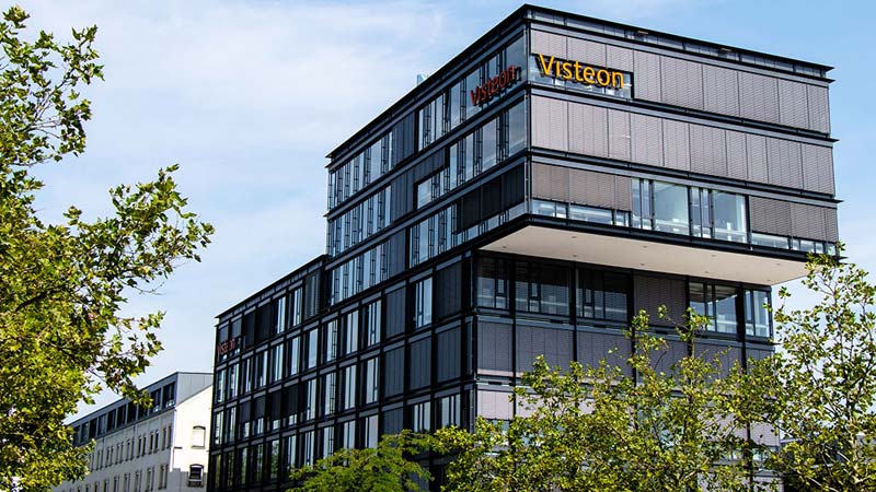
QuickFacts
Property: Office building
Location: Karlsruhe
Floors: 8
Height: 25,4 m
Safety stairway: 1
Fire service lift: 1
Fire alarm system: Yes
Sprinkler system: No
Keeping escape routes free from smoke
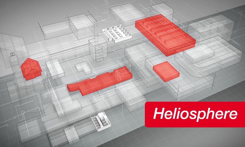
It is becoming increasingly difficult to find free space for new buildings in Germany’s cities. This is well known in the classic residential area. However, it is also becoming increasingly difficult for companies to find suitable areas for use in the inner city. Office buildings are therefore usually built upwards and fall under the provisions of the high-rise directive. As building heights increase, planners and architects are confronted with high fire protection requirements. The new Visteon office building in Karlsruhe is a showpiece for safe escape routes in high-rise buildings. The technical implementation of all specifications offers solutions that can also be applied to many other construction projects.
Safety stairway and fire service lift in the building
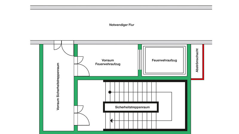
Safety stairways are characterised by the fact that they remain usable for a certain period of time in the event of a fire. This is vitally important for escaping persons and the fire service. The fire service lift allows access to bring fire-fighting equipment and personnel safely and quickly to the respective floor. In addition, safe anterooms and the fire service lift can be used to bring people to safety who cannot escape via the safety stairway. With a total of 8 floors and a height of just over 25 m, the Visteon office building falls under the requirements of the high-rise directive. A safety stairway and a fire service lift are therefore required. The office rooms connect to the internal safety stairway via necessary corridors and anterooms on the floors. The fire service lift anteroom opens into the safety stairway anteroom – an arrangement increasingly chosen by architects to use the space as efficiently as possible.
The following essential requirements must be observed so that the internal safety stairway, fire service lift and respective anterooms also remain smoke-free and usable in the event of a fire: (Note: The requirements described apply specifically to this building.)
- An anteroom is to be arranged on each floor in front of the internal safety stairway and in front of the fire service lift.
- Access to the usage units is via necessary corridors on the floors.
- T30 RS doors are required in each case in front of the safety stairway and the fire service lift as well as between the anteroom and the necessary corridor.
Technical measures
The ingress of smoke in the internal safety stairway, fire service lift and anterooms must be prevented with systems for generating overpressure (smoke protection pressure systems). Since there is only one internal safety stairway in this property, operational back-up units take over the function for maintaining the overpressure in the event of a failure of the system. The redundancy requirements concern the supply air fans for the safety stairway (2 fans, parallel).
A supply air fan is sufficient for the fire service lift. The air flow velocity must amount to least 2.0 m/s through the open doors of the safety stairway to the anteroom and from the doors of the anteroom to the necessary corridor. It must amount to at least 0.75 m/s through the open fire service lift anteroom doors. The maximum door opening force on the doors of the internal safety stairway and the anterooms may amount to a maximum of 100 N, measured at the door handle. A minimum pressure of 15 Pa must not be exceeded in the safety stairway and the fire service lift. The smoke protection pressure system is automatically triggered by the fire alarm system. It must immediately build up the required overpressure after being triggered. The building requires a safety power supply system. In case of failure of the general power supply, it takes over the operation of the safety-related building equipment – especially the smoke protection pressure system.
Design and functionality of the smoke protection pressure systems
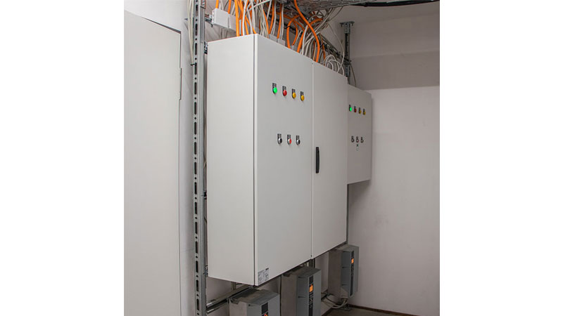
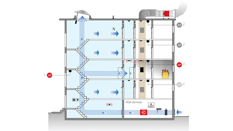
The supply air fans and both control cabinets of the smoke protection pressure systems are located in the RDA central unit in the basement. This is a separate room with F90 walls. In case of smoke detection, the two smoke protection pressure systems are automatically triggered by the fire alarm system. The supply air fans then convey fresh air into the safety stairway and fire service lift.
1) Safety stairway
There is an air injection point for supply air on the basement floor of the safety stairway. Thanks to the spacious stairway geometry and the existing stairwell, there is no need for another injection point on other floors. A supply air volume flow of approx. 22,000 m³/h flows into the safety stairway via this injection point in the event of a fire. Fresh air constantly flows through the stairway via the automatically opened skylight dome on the top floor to dilute and flush out any smoke gases that may have penetrated the system. The controlled overpressure that builds up in the stairway prevents smoke penetration at a very early stage and ensures that the escape route is kept smoke-free.
The smoke protection pressure system also automatically opens a controlled outflow opening on the fire floor, through which the supply air escapes into the open. An actively controlled outflow shaft was used in this office building for this purpose due to a lack of space. The required differential pressure regulation in the safety stairway is carried out with an actively controlled system. Differential pressure sensors ensure the continuous monitoring of the pressure situation in the area to be protected. This allows the system to respond to changing conditions and it enables organised smoke control. Door opening forces are not exceeded as a result.
The smoke protection pressure system adapts the supply air volume flow to the respective situation. This is done by controlling the fan with a frequency inverter. Escaping persons and the fire service require doors to be opened and closed. This results in constantly changing pressure conditions in the stairway. The smoke protection pressure system must respond to this within a short period of time (3 sec.) with sophisticated differential pressure regulation. The exit door on the ground floor has a special influence on the functionality of the system. It is equipped with an overhead door closer to ensure that it closes securely when the smoke protection pressure system is in operation, even against the overpressure. This prevents an unnecessary leakage area and the overpressure can be generated in the safety stairway. The integrated ventilation function of the smoke protection pressure system also allows the ventilation of the stairway as required at high temperatures. This function is particularly recommended for internal safety stairways, as they do not have any opening windows due to the pressure ventilation.
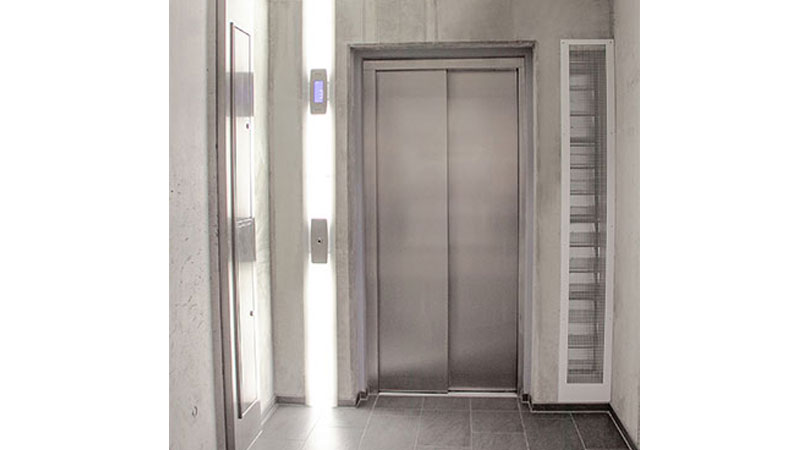
2) Fire service lift
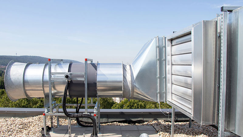
Helios RDA in the fire service lift
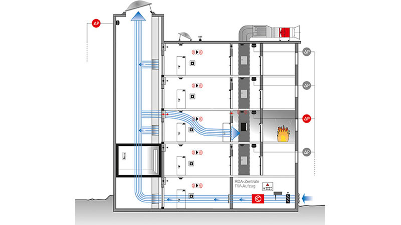
Schematic illustration of a smoke protection pressure system in the fire service lift. Shown here with supply air shaft in the lift.
Clever solution: Outflow through actively controlled outflow shaft
The controlled outflow opening can only rarely be realised via windows as facade outflows, especially for high or free-standing properties, complex building geometries, and for buildings in regions with strong winds. In these cases, an outflow shaft must be taken into account during planning. This is used exclusively for the smoke protection pressure system outflow and functions independently of wind influences. With this type of outflow, the supply air volume flow is discharged immediately after flowing through the door, by means of a vertical outflow shaft. The building geometries and the internal arrangement of the corridor in the Karlsruhe Raumfabrik also required a vertical outlet shaft. This is directly adjacent to the necessary corridor. It was imperative that the outflow shaft be designed with the appropriate fire resistance. The air flows in through smoke extraction dampers on the respective floors. The system must ensure that only the smoke extraction damper on the fire floor is opened. All other scenarios that would result in the opening of additional smoke extraction dampers on other floors are blocked in the control system.
The specialist planners and architects were faced with a particular challenge due to the limited space for the system technology and the outflow shafts: Outflow shafts must generally be designed with cross-sections of up to 1.50 m² as only the slight overpressure from the stairway or fire service lift is available for the outflow of the entire air volume after passing through the door. In order to meet the requirements for a maximum door opening force of 100 N, pressures of only 30-40 Pa are usually set. This overpressure must be sufficient to convey the door flow volume of approx. 18,000 m³/h through the outlet shaft. Large shaft cross-sections are usually the unpleasant consequence. An actively controlled outflow shaft was used in order to be able to make the cross-sections much smaller in this office building.
Actively controlled outflow shaft
Schematic illustration of a smoke protection pressure system with actively controlled outflow shaft.
The air here is also discharged via a vertical outflow shaft. The air pressure losses are overcome by a fan In this process. This is positioned on the shaft and extracts the air from the fire floor.
By using this technology, an outflow shaft (also with a small cross-section) can even be used in high-rise buildings. A fan in temperature class F300 was used, which is regulated by means of a frequency inverter depending on the pressure conditions and fire floor. The differential pressure measurement takes place directly in front of the extraction point in the necessary corridor for precise extraction control. Therefore, a differential pressure sensor with pressure tapping point must be installed in the necessary corridor on each floor (however, mounting the actual sensor in the anteroom). In the event of a fire, only the relevant sensor on the fire floor is evaluated by the smoke protection pressure system. In order to reliably avoid pressure peaks when doors open and close, a fast-regulating bypass damper is positioned between the fan and the outflow shaft. The control system for the actively controlled outflow shaft is housed in a separate control cabinet. When adjusting, careful coordination of the supply air fan and the fan on the outflow shaft is necessary in order to always be able to comply with the maximum permissible door opening force. The outflow from the fan is free of combustible objects and inaccessible to persons, as increased temperatures at the air outlet can be expected under certain conditions.
Summary
Smoke protection pressure systems have proven their worth as a reliable technology for smoke control in safety stairways and fire service lifts in recent years. The exact requirements usually differ for the respective buildings, however, they are described as a priority e.g. in the high-rise directive and the MVV technical construction regulation. Individual solutions are usually required for the optimal fulfilment of requirements. Therefore, all persons involved should reach an agreement at a very early stage of planning. Solutions such as the actively controlled outflow shaft offer planners and architects many options and keep the space required for the system technology to a minimum. Reliable system technology for a high level of safety can thus be integrated discreetly, cost-effectively and inconspicuously in the building. Futuristic, creatively designed buildings and the safety requirements can be cleverly combined and are not a contradiction in terms.
Images: Helios Ventilatoren

